Stitched Video
Stitched Video is an entity that can calibrate a camera rig containing one or more cameras. The cameras can then be stitched together during runtime using different techniques. Common uses cases for the Stitched Video are to remove the fish-eye effect for one camera or to make a larger stitched video by combining multiple cameras.
Another way to think about the use case for Stitched Video is that where a 2D Video presents video like one would see video on a TV or phone screen the Stitched Video allows to look out from the camera like if the viewer were at the center of the camera rig. In this way of thinking about it, the purpose of a Stitched Video is to visualize the world as correctly as possible based on the cameras that are part of it.
A Stitched Video requires calibration to work properly.
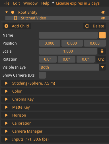
Stitching
The Stitching tab contains settings for controlling the stitching of the video.
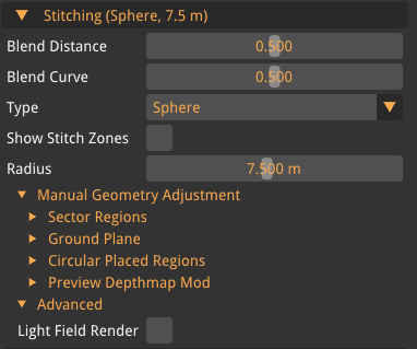
- Blend Distance
-
Given two cameras with some overlap between them, Blend Distance sets how much of the overlap is visible. Value goes from 0.0-1.0 where 0.0 is a sharp line (no visible overlap) and 1.0 shows the full overlap.
- Blend Curve
-
The overlap zone is the area where video is shown from both cameras. Blend Curve describes the blending function across the overlap zone.
- Type
-
The stitching can be viewed on different surfaces. The currently supported types are:
-
Sphere
-
GPU Auto
-
Model
-
External
-
- Show Stitch Zone
-
When enabled, it will show where the stitch between different video feeds is located, can be helpful to have enabled when changing stitch settings.
Type specific settings
Some specific settings are only visible when a type is selected.
- Radius(Sphere specific)
-
Sets the size of the sphere which the video is displayed on. It is recommended to set the size to the distance of the object most likely to be looked at.
- Lock Auto-Stitch(GPU Auto specific)
-
When enabled, freezes the current depth map and stops the algorithm from updating the stitch geometry. Useful for locking in a result you are happy with, or for testing under static conditions.
- Reset(GPU Auto specific)
-
Clears the current depth state and the temporal smoothing buffers so the algorithm restarts analysis from scratch.
- Add (Model specific)
-
Adds one or more of the selected primitives, the following are supported:
-
Box
-
Sphere
-
Quad
-
Model From File
-
All model types have settings regarding transform, scale, and rotation. There are other settings that are specific for this type called Entity transform which can connect this primitive to other entities transform.
Quad has a button called Set As Calibrated Floor, if a horizon calibration has been made it will automatically set the quad to the height of the calculated floor.
Manual Geometry Adjustment
Manual Geometry Adjustment lets you override or supplement the automatic stitch geometry by defining regions of the panorama where the distance and blending of the projection surface are set by hand. The combined adjustments are baked into a small depth/weight texture that the renderer samples when projecting the cameras. Regions can be layered, and the preview at the bottom shows the resulting depth map.
Sector Regions
A sector region is an angular slice of the panorama with a fixed projection distance. Use sectors when a portion of the view should sit at a different depth than the rest.
- Add
-
Adds a new sector region with default values (angle 0°, size 25°, blend 0.5, distance 3.5 m).
- Angle
-
The center azimuth, in degrees, where the sector is placed. 0° is forward; values wrap at 360°.
- Size
-
Total angular width of the sector, in degrees. Default 25°.
- Blending
-
Edge feathering of the sector. 0.0 is a hard edge; 1.0 fades smoothly across the entire width. Default 0.5.
- Distance
-
The projection distance for this sector, in meters. Logarithmic slider, range 0.4–800 m, default 3.5 m.
Ground Plane
A ground plane is a tilted plane placed below the rig. Use it to project the floor at a consistent distance regardless of camera angle.
- Active
-
Enables the ground plane.
- Angle
-
Pitch angle of the plane from vertical, in degrees. Range 10–70°, default 45°.
- Height
-
Distance of the plane below the camera, in meters. Range 0.5–100 m, default 1.5 m.
- Blending
-
Edge feathering of the plane. Range 0.0–1.0, default 0.5.
Circular Placed Regions
A circular region is a sphere placed at a specific 3D position. Use it to override projection at a localised point in the panorama (e.g. a nearby pole or vehicle part).
- Add
-
Starts an interactive placement: click once in the 3D view to set the region center, then click again to set the radius.
Color
Color is described in Color Handling.
Chroma Key
Chroma Key is described in Chroma Key.
Matte Key
Matte Key is described in Matte Key.
Horizon
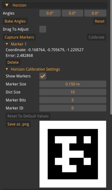
Horizon can change the rotation of the stitched video to better align the video with the real world if the cameras are tilted. The horizon can be calibrated with the use of an aruco marker. For the calibration, the marker on the backside of the calibration board can be used or it can be printed.
| When printing a marker, make sure it is printed on a flat stable surface! |
At least three markers need be captured for the calibration, but we recommend using more captures to get a better calibration. When three markers have been captured the button "Calibrate" will be available, when pressed, it will rotate the stitched video. The video might not be centered where the user wants it, the manual horizon values can then be used to make fine-tunings.
- Angle
-
The angle of each axis that the stitched video will be rotated around.
- Bake Angle
-
This button will take the horizon angles and bake them into the camera rig settings. This is recommended after horizon calibration has been made.
- Reset
-
Resets the applied horizon.
- Drag To Adjust
-
When enabled, make it possible to change the horizon by clicking and dragging the view.
- Capture marker
-
When pressed, captures a visible marker.
- Calibrate
-
Runs the calibration algorithm and changes the horizon. At least three markers must have been captured.
- Marker Position
-
Each marker that has been captured will be shown here along with the position. The marker can be deleted with the Delete button.
Horizon Calibration Settings
- Show marker
-
When enabled it will show the captured marker in the 3D world.
| The rotation may not always be accurate, however the rotation is not used in the algorithm so it can be discarded. |
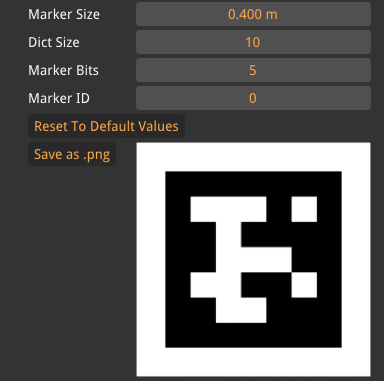
- Marker Size
-
The size of the physical calibration board.
- Dict Size
-
The size of the dictionary with markers that will be created.
- Marker Bits
-
The number of bits in each dimension for the marker.
- Marker ID
-
The ID of the marker in the dictionary.
- Reset To Default Values
-
Resets to the default values.
- Save as .png
-
Saves the marker to a .png file.
Calibration
Calibration is used to calibrate the camera positions, this can be done with one camera or multiple.
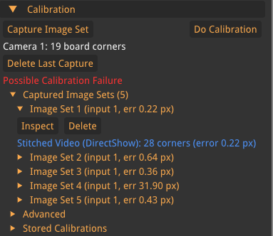
- Capture Image Set
-
Capture the current frame to use for the calibration.
- Do Calibration
-
Does a camera rig calibration with the currently captured images. It is available after at least one image is captured.
- Delete Last Capture
-
Delete the last calibration image taken, only appears after a minimum of 1 image has been taken.
- Capture Image Sets
-
This tab contains all the images taken of the calibration board and the pixel error for each image. The Images can also be inspected and deleted.
Advanced
Advanced settings for the calibration, recommended is to let them be the default value.
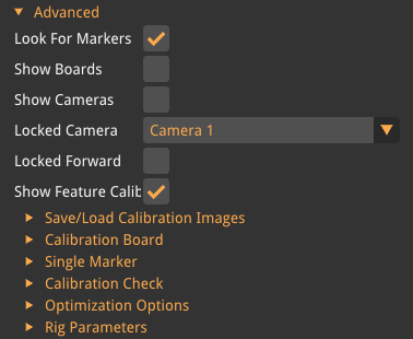
- Look For Markers
-
If enabled, the software will look for calibration boards and single markers.
- Show Board
-
Shows the captured location of the calibration board.
- Show Cameras
-
Shows the positions of the cameras in the 3D space in relation to each other.
- Locked Camera
-
Lock one of the cameras so the rest moves in relation to that camera.
- Locked Forward
-
Lock rotations of the camera selected in the above setting.
Calibration Board
Settings for how the calibration should look like, the supplied calibration board from Voysys use the default values.
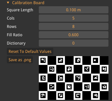
- Square Length
-
The width of each square on the calibration board.
If a calibration board has been printed it is important to measure the square size very accurately. - Cols
-
The number of columns of aruco markers.
- Rows
-
The number of rows of aruco markers.
The displayed calibration board might be flipped so the columns and rows may be inverted. - Fill Ratio
-
Set how much of the white area the aruco marker should cover.
- Dictionary
-
Set which pre-made dictionary to use.
- Reset To Default Values
-
Sets all values to the default.
- Save as .png
-
Save the calibration board image to a .png file for printing.
Single marker
Settings for the single marker detection, this marker is used for both calibrations and check calibrations.
- Marker Size
-
The size of the physical calibration board.
- Dict Size
-
The size of the dictionary with markers that will be created.
- Marker Bits
-
The number of bits in each dimension for the marker.
- Marker ID
-
The ID of the marker in the dictionary.
- Reset To Default Values
-
Resets to the default values.
- Save as .png
-
Saves the marker to a .png file.
Calibration Check
Calibration check can be used to analyse how good the calibration is, this is done by using the single marker on the backside of the calibration board. If no calibration board is available, it is possible to print one. A .png file can be downloaded from the Single Marker tab. Most of the settings are only visible after a calibration check has been made.
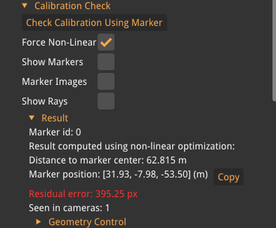
- Check Calibration Using Marker
-
Pressing this button while having an aruco marker visible by two or more cameras will give a value on how good the calibration is.
- Force Non-Linear
-
Force the solver to use Non-Linear equations to solve the problem.
- Show Marker
-
Show a marker where the software has detected them in the video.
- Marker Images
-
Show an image of the marker on the place the marker was detected.
- Show rays
-
Show the rays which were used to detect the marker.
Result
- Marker ID
-
Show which ID in the dictionary the detected marker has.
- Result Computed Using Non-Linear Optimization
-
Indicates that the marker position was solved by minimising reprojection error across cameras rather than by simple ray intersection. Shown only when the non-linear solver was used.
- Distance to Marker Center
-
The distance to the marker center.
- Marker Position
-
The calculated position of the marker.
- Residual error
-
The error of the captured marker, larger error means that the calibration is not good.
- Seen in Camera
-
Shows which cameras that detected the marker during the check.
Geometry Control
Aligns model geometry (primitives added under the Model stitch type) to a marker detected by Calibration Check. For each quad in the model geometry that has an Id, a button is available to align that quad to the detected marker’s position and rotation. If no quads with IDs exist, the section shows a hint to add one first.
Optimization Options
- Use AprilTag2
-
Uses the AprilTag 2 algorithm to detect the markers which can give a better result, however, will take more computation time.
Rig Parameters
Very advanced settings about how the camera rig is set up and should not be tampered with if you do know exactly what you are doing.
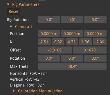
- Reset
-
Resets the rig parameters.
- Rig Rotation
-
Rotates the whole rig which includes all cameras.
Camera N
One subtree per camera in the rig. Most values are intrinsic/extrinsic calibration parameters and should not be hand-edited unless you know exactly what you are doing.
- Position
-
The camera’s position relative to the rig center, in meters (X, Y, Z).
- K
-
The camera’s intrinsic calibration coefficients (5-element distortion model). These describe focal length and lens distortion.
- Offset
-
The image plane offset from the optical center, in normalised coordinates. Corrects for sensor misalignment.
- Rotation
-
The camera’s orientation as Euler angles in degrees.
- Max Theta
-
The maximum half-angle from the optical axis that the camera is allowed to project, in degrees. Limits the field of view to avoid sampling invalid peripheral pixels.
- Horizontal FoV
-
Read-only. The horizontal field of view in degrees, computed from the K matrix and sensor width.
- Vertical FoV
-
Read-only. The vertical field of view in degrees, computed from the K matrix and sensor height.
- Diagonal FoV
-
Read-only. The diagonal field of view in degrees.
Calibration Manipulation
Tools to re-orient the entire rig relative to one chosen camera. The settings are only visible inside a Camera N subtree.
- Center Position On Camera N
-
Translates the rig so that the selected camera sits at the origin. All other cameras shift by the same vector, preserving relative positions.
- Center Camera N Rotation on New Forward
-
Rotates the whole rig so that the selected camera’s optical axis aligns with the New Forward direction below.
- New Forward
-
The target forward direction (quaternion) used by Center Camera N Rotation on New Forward.
Stored Calibrations
The software ships with some premade calibration for common cameras, by selecting one in the dropdown menu it sets all camera rig parameters.
More calibrations can be added to the dropdown menu by specifying a path to a folder containing '.camera' files. More information is described in Application Settings under "Camera Calibration".
Captured Image Sets
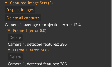
- Inspect Images
-
Open up a new GUI for inspecting the captured images.
- Delete All Captures
-
Deletes all the captured images.
- Frame N
-
Each tab shows information about the captured frame.
Review Calibration
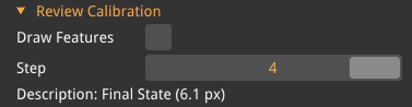
Step through the intermediate states recorded during the most recent calibration run. Only visible after a calibration has been made and when the history contains more than one step.
- Step
-
Selects which step in the calibration history to view. Step 0 is the initial guess; later steps show successive refinements.
- Description
-
A text label describing the current step (e.g. Initial guess, Refining cameras, Converged).
Inputs
Input is described in Video Inputs.